Engineers must refine their foundational understanding of process safety in order to avoid common misconceptions about safety instrumented systems, including safety integrity level (SIL) definitions
Learnings from major industrial process accidents occurring over the past half century have driven awareness of functional safety and resulted in the development of two performance-based standards for manufacturers in the chemical process industries (CPI). These standards, introduced by the International Electrotechnical Commission (IEC; Geneva, Switzerland; www.iec.ch), are known as IEC 61508 and 61511.
A safety integrity level (SIL) is utilized as a measurement of required risk-reduction targets, as well as a way to represent achieved risk reduction. Although the functional safety standards have been in existence for many years, there are many common misconceptions around industry standards, as well as around the concept of SILs themselves.
Introduction to functional safety
Safety, in its most basic form, can be defined as freedom from unacceptable risk. Risk is a function of the likelihood of an incident occurring combined with its resulting consequence — specifically, a personal injury, loss of life or damage to the environment and equipment. The higher the likelihood and consequence, the higher the risk involved.
Functional safety is a part of the overall safety that depends on a system or equipment actively and correctly operating in response to its inputs to minimize risk. Safety instrumented systems (SIS) provide an active means of supporting functional safety, with a sensor to detect a dangerous condition and a logic solver to evaluate scenarios and activate a final element to respond and mitigate or reduce the consequence of the hazardous event. Such systems are commonly used in the CPI in accordance with IEC 61511 and 61508. A simple application example could be protection against vessel overpressure via a safety instrumented function (SIF). This would include pressure sensors set to detect high pressures within a vessel and the logic solver to determine whether the pressure within the vessel has become too high, in which case a final element is activated to open, relieving vessel pressure.
SIL and risk reduction
The functional safety standards IEC 61508 and 61511 have defined the measurement of performance required for a SIF. These standards provide guidance on how to specify a target level of risk reduction, as well as how to scrutinize the relative level of risk reduction provided by a SIF, to bring risk down to a tolerable level.
Initially, risk is measured by how likely it is that a given event will occur and how severe it would be; in other words: how much harm could it cause? There are different tools to quantify risk that are available to engineers, including the hazard and operability study (HAZOP), process hazard analysis (PHA) and so on. After the hazard’s risk is quantified, it is compared with the end user’s tolerance for risk. If the level of risk is greater than the tolerable level of risk, reduction measures are identified and evaluated to determine if risk can be reduced to an acceptable level. Often, active measures, such as basic process control system (BPCS) alarms or operator intervention, provide adequate levels of risk reduction. If so, a SIS is not required. However, if risk reduction must be reduced by a factor of greater than 10 (a risk-reduction factor, or RRF >10), a SIS should be used, or the process should be redesigned to reduce inherent risk further. Figures 1, 2 and 3 illustrate risk levels and potential system requirements for low-, medium- and high-risk cases.
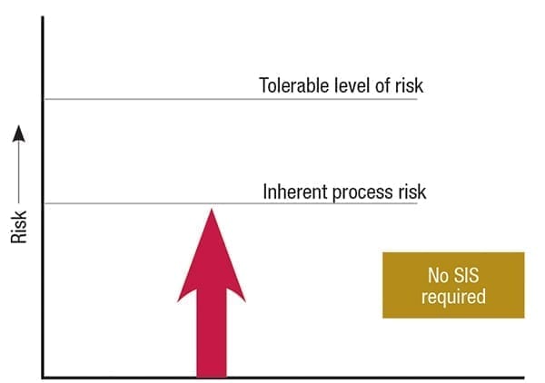
FIGURE 1. Low-risk case: In this case, the inherent process risk is lower than the operator’s tolerable level of risk. Thus, no additional risk reduction is required
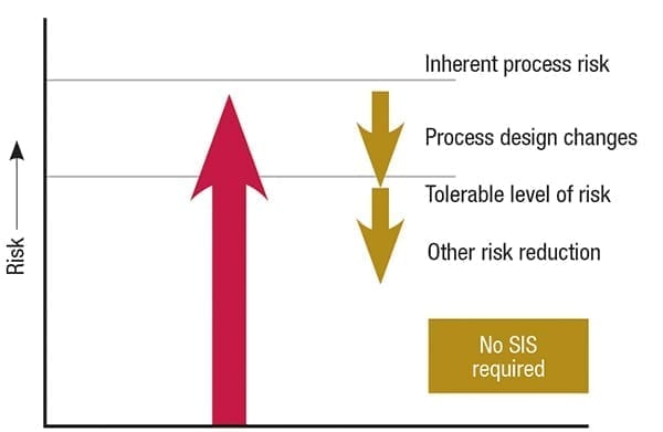
FIGURE 2. Moderate-risk case: Here, the inherent process risk is greater than the operator’s tolerable level of risk, so risk reduction is required and met via means other than a safety instrumented system
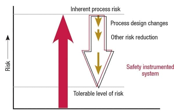
FIGURE 3. High-risk case: The inherent process risk is much greater than the operator’s tolerable level of risk. Thus, risk reduction means, which may include design changes and other layers of protection, are implemented in addition to a safety instrumented system
Safety instrumented systems consist of one or multiple SIFs that address particular hazards. A SIF within a SIS consists of one or more sensors, logic solvers and final elements designed to actively detect and respond to a potentially dangerous condition, thus mitigating or reducing the consequence of the hazardous event (Figure 4). Common CPI applications include emergency shutdown, blowdown, vents to flare and so on.
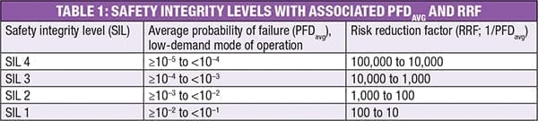
IEC 61508 and 61511 set out the requirements for ensuring that systems are designed, implemented, operated and maintained to the required SIL. Four SILs are defined according to the risks involved in the application, with increasing risk reduction required by increasing SIL, as shown in Table 1.
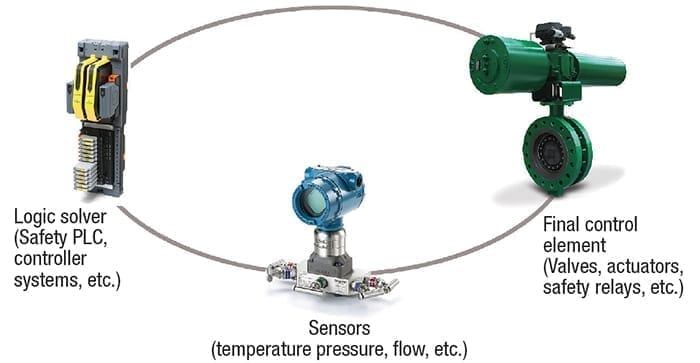
FIGURE 4. Common elements within a safety instrumented function (SIF) include sensors, actuators, safety relays, programmable logic controllers (PLCs) and more
Challenges and misconceptions
Electrical, electronic or programmable electronic systems (E/E/PE) can carry out a multitude of safety functions. The challenge is to design safety systems in such a way as to prevent dangerous failures or to control them when they arise. However, during the design phase, much of the focus has become around the selection of hardware with failure rates that meet a target SIL. This has led to some common misconceptions around the proper application of the functional safety standards and SIL in the CPI. Some of these misconceptions are described in the following sections.
Misconception: The IEC 61511 and 61508 standards will direct exactly how to design, install and operate a safe process. IEC functional safety standards are performance-based, not prescriptive. This means that they do not specify process design conditions or acceptable materials of construction, recommended operating conditions, or predetermine protective functionality. Instead, the standards publish the framework for manufacturers (IEC 61508) and process industries (IEC 61511) that defines a safety lifecycle approach to safety systems covering the analysis, design, implementation, operation and decommissioning of a SIS.
For example, end users are required to determine their tolerable level of risk reduction and design a process with the appropriate rigors, processes and competencies to ensure that systematic and random failure modes are minimized.
Misconception: Using a SIL-2-capable device (such as a transmitter or final element) is all that is needed to comply with functional safety standards. Safety integrity levels apply to the entire SIF loop, which consists of sensors, logic solvers and final elements. The SIL achieved is a function of the average probability of failure upon demand ( PFD avg) of the combined SIF devices, as well as the systematic integrity of each device.
For example, if there is a SIF consisting of the following elements: logic solver (SIL 3 capable) + sensor (SIL 2 capable) + final element (SIL 1 capable), the maximum SIL capability achievable is SIL 1, regardless of PFD avg achieved.
Misconception: If all the products specified are SIL 3 certified products, the SIL 3 target is met. Device certificates are an indication of SIL capability, meaning that the device is systematically capable of meeting SIL 3 only when the proper hardware-fault tolerance and PFD avg are also met for the SIF (including all devices in the entire loop, combined). To verify a SIL, the following needs to be considered:
- Systematic integrity (all elements need to have a systematic capability (SC) of 3 for a SIL 3 loop)
- Random integrity (PFDavg)
- Architectural constraints (hardware-fault tolerance, or HFT)
It is important to also note that the higher the SIL target, the more redundancy is typically required.
Misconception: Using an industry-leading SIL verification tool to select devices that meet the SIL target is sufficient for designing the SIF. Making the “numbers” (SIL verification) work is not a guarantee that the devices selected are appropriate for your process. Proper selection is required, and should consider process specifics, safety-function performance requirements and environmental conditions to safeguard against systematic failures from material incompatibility or undersized or misapplied hardware.
One relevant example focuses on the part of the SIF that generates the most failures. Statistically, the final element makes up 50% or more of the dangerous undetected failures in a SIF, as shown in Figure 5 [1]. In process applications, the logic solver and sensors are consistently self-testing and self-reporting — for example, a pressure transmitter takes measurements and reports them to the logic solver, which analyzes the measurements and decides whether to engage the final element. Meanwhile, the final element is typically in low demand. Thus, it remains in one position for most of its installed life until activated to perform its safety function. The final element also is in contact with the process fluid, making it susceptible to buildup within the valve and, thus, potentially unable to respond to a demand. This underlines the importance of not only properly testing the final element to ensure operation, but also makes the proper sizing, selection and engineering critical to meeting the safety function.
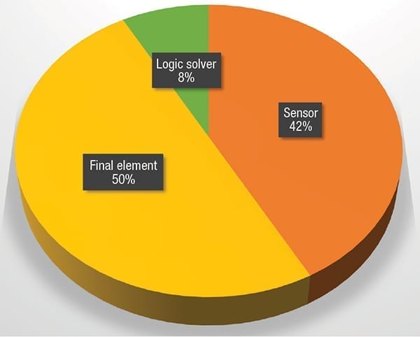
FIGURE 5. Final elements are the largest contributor to unplanned safety-system failures [1]
Misconception: If the SIL target is met in the initial design, it is good forever.Actually, proper testing of the SIF is required periodically to uncover dangerous undetected failure modes and maintain the SIL through the deemed operating lifetime (mission time). Once the SIF is installed, the equipment follows the normal bathtub-shaped reliability curve, which has a constant failure rate during its useful life. Thus, the SIL capability degrades over time in a predictable manner. To maintain the SIL required, the SIF must be tested periodically to prove that it can meet the safety function when called upon. These tests are called “proof tests” and are intended to identify dangerous undetected failure modes that are not otherwise detectable under normal process conditions through the mission time of the SIF.
Proof tests may include visual inspection, as well as performance testing, to meet safety-function specifics. For a final element, this commonly includes sending a trip signal from the logic solver and performing a full stroke from its normal to safe position, as well as verifying the stroke time. If tight shutoff is required, shutoff and leak rates would be tested. Devices and final elements that utilize diagnostics may be used to uncover additional degradation not otherwise apparent by visual inspection, such as the implementation of digital valve controllers on final elements to detect an increase in torque.
Performing proof testing often requires taking a device out of service. This can impact availability of operations. For the final element, a bypass can potentially be installed around the final element to enable proof testing without impacting operations. However, in some cases, space restrictions or installation cost with large line sizes makes installing a bypass more prohibitive. To maintain a SIL throughout the mission time, a partial stroke test is an option to supplement proof tests. Partial stroke tests can be performed in service while the process is running, stroking the final element over a portion of its total travel. This exercises the valve and proves that it can break out from its normal position, detecting a portion of the dangerous undetected failure modes of the final element. This test can be used to safely extend the proof-test interval or to meet required SIL with existing test intervals.
Although systems are usually complex, making it impossible in practice to fully determine every potential failure, proof testing is nevertheless essential to rule out as many options as possible and meet the SIL target through the mission time.
While SIS concepts and standards are becoming more well-recognized in the CPI, misconceptions still remain. Improved awareness and proper action will help to avoid associated systematic failures and to ensure a safer facility. ■
Edited by Mary Page Bailey
Reference
1. DNV GL A/S, Offshore Reliability Database (Oreda) Handbook, 2015.
Author
 Afton Coleman is the senior marketing manager at Emerson for Fisher Digital Isolation Solutions (205 S. Center St., Marshalltown, IA 50158; Phone: +1-641-754-3439; Email: [email protected]). She leads a product management team that works on the development of complete SIS final-element solutions. Coleman has supported functional safety and process application needs for multiple process industries, as well as the nuclear power industry, for over 14 years in her different roles with Emerson. She is a Certified Functional Safety Professional (CFSP). Coleman has a B.S.Ch.E. from the University of Iowa and an M.B.A. from Iowa State University.