Compliance with air-pollution regulations requires ongoing effort. Follow these recommendations to assess competing options and optimize system design while minimizing cost and risk
The goal of air-pollution control (APC) is to limit the amount of pollutants entering the environment. These include particulate matter (PM), acid gases, greenhouse gases, organic vapors such as hazardous air pollutants (HAPs), volatile organic compounds (VOCs), non-condensed gases (NCGs), aerosols, dioxins, oxides of nitrogen (NOx), metals and others. This article focuses on pollution from combustion sources, but the equipment discussed here can be applied to other applications, as well.
It has been said that a good engineer can build for a dime what any fool can build for a dollar. The same can be said for savvy plant managers. Smart chemical process industries (CPI) firms do their homework before installing air-pollution control systems [ 1]. They consider process changes (such as switching to the production of low-VOC coatings), plant-siting considerations (for instance, avoiding non-attainment areas, or those with complex terrain that may require tall stacks), and better capture systems (to reduce the volume of fume to be treated) before making a final decision on hardware. Nonetheless, other choices must be made — such as choosing a wet or dry system, and tradeoffs between cost of power versus capital — to optimize the final system’s design.
Removal of particulate matter
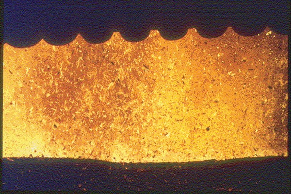
FIGURE 1. This wood-fired boiler furnace with a pneumatic spreader stoker shows lots of wood particles and burning embers above the grates
Tom McGowan
Particle loading in the fluegas from any industrial process is measured in grains/dry std. ft3 (grains/dscf) or mg/dry std. m3 (mg/dscm) or mg/normal m3. The particle loading in the gas will vary widely depending upon a number of factors, including the gas velocity, particle size, particle density and the nature of the upstream process and feedstock. The smaller the particle, the more easily it is carried by the fluegas, even at relatively low gas velocity. As the gas velocity increases, larger particles can be carried by the fluegas stream, and the number of particles of all sizes that can be carried increases (Figure 1).
U.S. federal and state regulations related to particulate matter vary with the process and the scale of the equipment. In the U.S., historic state and federal particulate limits (for example, the Resource Conservation and Recovery Act, or RCRA) were typically 0.08 grains/dscf (180 mg/dscm). By comparison, newer limits are generally at or below 0.02 grains/dscf (45 mg/dscm). This requires better, more-expensive controls, and better design, operation and maintenance strategies. Coal- and wood-fired boilers [ 2], and cement kilns are some examples of applications with high particulate levels upstream of the APC systems.
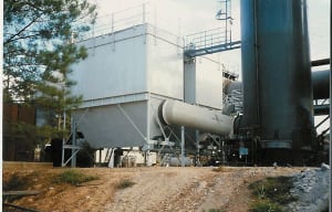
Dry-particle-removal systems. When it comes to removing dry particulate matter from fluegas streams, the options include cyclones, fabric filters (Figure 2), and electrostatic precipitators (ESPs). If acid gases are present in the fluegas stream, these devices must be insulated to keep their shells above the acid dewpoint. The American Society of Heating, Refrigeration and Air Conditioning Engineers (ASHRAE) and other sources publish charts, graphs and calculators to determine SO2 and HCl dewpoints. If the wall temperatures of these pollution-control systems fall below the acid dewpoint temperature, acid vapors may condense on the metal surface and this will result in high rates of corrosion.
Wet-particle-removal and vapor-removal systems. When unwanted pollutants must be removed from the fluegas stream, the options include wet cyclones, venturis (Figure 3), wet electrostatic precipitators (WESP), and ionizing wet scrubbers (IWS; Figure 4). With regard to particulate emissions, venturis (Figure 3) tend to have limited ability to remove fine particles, and they experience exponentially higher pressure drops when forced to remove particulate matter. In recent years, with tighter U.S. Environmental Protection Agency (EPA) limits, the use of venturis as a standalone particulate-removal device has fallen out of favor.

FIGURE 3. Shown here is a venturi scrubber and slinger tank/acid gas absorber with an internal mist-elimination system
Due to more stringent and complex regulations for multiple pollutants, different APC systems are frequently used in series. For instance, a venturi scrubber may be used to remove particulate matter, followed by a packed tower to remove acid gases, followed by a mist-elimination system to reduce droplets in the stack (Figure 3).
The wet-versus-dry decision is far from clear cut. Some industries tend to use dry systems (for example, the ESPs used in coal-fired power plants), while others prefer wet systems, such as an ionizing wet scrubber (Figure 4). Preferences change over time with more-stringent regulations. Disposal options for the removed particulate matter (that is, the resulting dry dust, wet sludge, or stabilized mixture that is formed during treatment) is another major factor in decision making. Cement kilns are an example, where baghouses are used to capture cement kiln dust (CKD), which is a salable product, while a wet capture system would form unsaleable (and system-fouling) cement solids.

FIGURE 4. In this two-stage ionizing wet scrubber, particles are charged, then removed on grounded plates and on packing; a periodic wash flushes and cleans the plates and packing
For dry ESPs, the resistivity of the collected flyash is an issue, and changing the coal feed source can change the resistivity and associated particulate-removal efficiency. Dust with high resistivity can be held too strongly to the grounded ESP plates, while low-resistivity dust may become re-entrained in the gas stream. By comparison, an IWS is immune to the effects of flyash resistivity.
Each of the devices mentioned here has its own characteristic operating curve. Figure 5 provides a comparison for an IWS, baghouse and dry ESP. Note that the collection efficiency for all of these devices begins to fall off for smaller particles, with the IWS having the least-rapid decay of its efficiency curve. IWS are frequently used in series with two or three in a row, in part, to maintain removal efficiency during their required periodic wash cycle; in this scenario, a downstream unit operates while the upstream unit is being washed down.

Figure 5. In this graph of particle size versus removal efficiency, three of the most commonly used APC devices experience a decline in collection efficiency as the particle size of the pollutants falls. This phenomenon is least pronounced for the ionizing wet scrubber (IWS)
Acid-gas removal
Combustion systems, chemical process operations, metals-recovery systems and incinerators produce acid gases, such as HCl and SO2. Acid-gas removal can be accomplished using either a wet or dry system.
Wet systems.The wet system generally has a higher removal efficiency and uses more nearly stoichiometric amounts of a basic (alkaline) reagent compared to the dry system. In general, wet systems use a basic material such as lime or NaOH (caustic) to neutralize and remove the acid. For wet systems, blowdown must be handled (generally limited to 5% total dissolved and suspended solids), and operators should note that publicly owned treatment works (POTWs) and sewers may have limits on the salt content and temperature of accepted discharge streams.
Fouling of spray nozzles is to be expected over time (Figure 6). Good design allows for nozzles to be pulled from the outside of the unit for easier maintenance. It is a good practice to bench-test nozzles — both new and after cleaning — with water, to make sure the spray pattern is what is expected. Use of small amounts of sequestering agents, like hexametaphosphate for lime fouling, can significantly reduce nozzle plugging. In some CPI applications, an acid gas (such as HCl) can be captured during fluegas treatment, and then concentrated and reused in the process.
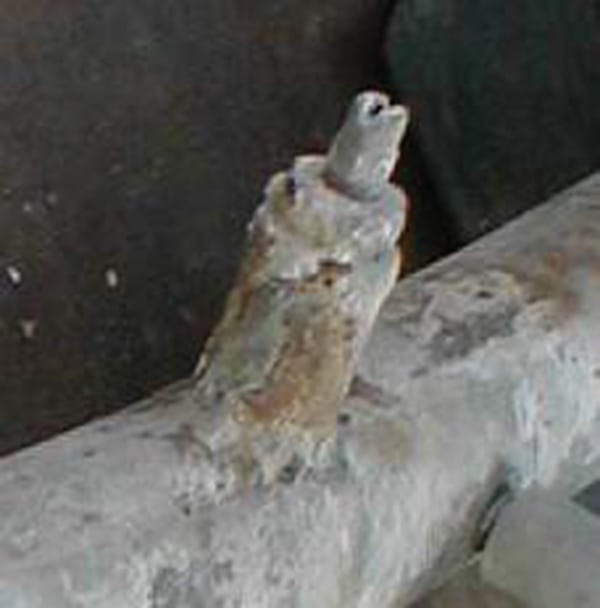
FIGURE 6. Fouling of spray nozzle by lime solids requires periodic changeout or chemical treatment
Tom McGowan
Dry systems. Dry systems typically rely on one of two approaches — they inject powered lime or sodium-based reagents upstream of dry fabric filters or ESPs, or they spray a lime slurry into the spray-drying tower. These reagents adsorb and react with acid gases, removing them from the fluegas in the form of solid particles.
While not an acid gas, CO2 produces greenhouse gas issues. For each pound of carbon burned in a CPI process, 3.67 lb of CO2 is released. Using engineering principles to maximize fuel economy, maintain insulation, and carry out regular steam-trap maintenance can help to reduce the CO2 burden. While EPA has put forth limits on utility power plants, in the CPI, CO2 emissions are driven principally by longterm corporate goals rather than regulations.
Much has been said about CO2 capture. However, this is a costly undertaking. And, parasitic power loss for associated utility operations has been estimated to be in the range of 30% for amine-based systems including the cost of CO2 compression, and some consider burning 30% more fuel to capture CO2 a questionable practice.
NOx control
EPA requires control of NOx, as NOx reacts with organic vapors in the presence of sunlight to produce ground-level ozone. The low-cost way to limit NOx is to do so upstream in the combustion process, for instance, via low-NOx burners, and low-oxygen firing systems [ 3]. This article focuses on the downstream or end-of-pipe methods that are most widely used.
The NOx levels resulting from any combustion operation are a function of a number of factors, including flame geometry, oxygen level, mixing, temperature, time and nitrogen level in the fuel. All conventional combustion systems produce “prompt NOx,” and “thermal NOx.” In addition, “fuel NOx” is created when the fuel contains nitrogen.
Some processes, such as cement and lime kilns, preheat air in the range of 2,000°F and operate at very high temperatures. NOx levels of 2,000 ppm are not unusual. “Normal” NOx levels from standard burners (for instance, those used in packaged boilers) are in the range of 100–200 ppm. So-called low-NOx burners typically produce less than 50 ppm of NOx, with ultra-low-NOx burners producing NOx at levels below 25 ppm. When preparing a permit application, use U.S. EPA AP-42 estimates [ 4] or conservative vendor quotes for NOx levels.
Fluegas recirculation is a popular NOx-reduction method for packaged boilers, both new and retrofit. With such a system, low-oxygen fluegas is injected into the burner along with fresh combustion air. When carried out properly, there is little change in efficiency and boiler output. However, it takes more sophisticated controls to maintain sufficient oxygen levels to ensure combustion while reducing overall oxygen levels with this system to minimize NOx formation.
Post-combustion control options to reduce NOx emissions consist of selective catalytic reduction (SCR) and selective non-catalytic reduction (SNCR), both of which involve the injection of a chemical reagent (ammonia or urea) into the fluegas stream. SCR processes typically operate at lower operating temperatures, ranging from 450 to 700°F. By comparison, SNCR processes operate at higher temperatures (just downstream from the furnace), ranging from 1,600 to 2,100°F. SCR systems are more efficient in NOx removal than SNCR systems, but have much higher capital costs. Computational fluid dynamics (CFD) modeling (Figure 7) is frequently done for SNCR systems, to help users to optimize injection points, enhance mixing and estimate NOx-removal efficiency. In general, CFD is not used as frequently for modeling SCRs, because such systems use a chamber to house the catalyst and the catalyst pressure drop helps to even out fluegas flow.

FIGURE 7. CFD modeling results are shown here for a large-scale boiler NOx-control application using a SNCR system. The colors are coded to show velocity. The green-yellow streams show the zones of NH3 regent injection and mixing with fluegas
VOC control
The primary non-transportation sources of VOC emissions are chemical process operations (such as reactions); storage and transfer (such as pumping and working losses and tank-breathing losses); manufacturing (solvents); and surface coating (spray painting and dipping).
Three primary control technologies are used for VOC: thermal oxidation; adsorption via activated carbon or zeolites (or both); and condensation. Biofilters can also be used in some applications. Choosing the right control for each application involves knowing the following:
The control system includes the hoods, ductwork, fans and controls needed to capture and deliver the VOCs to the control device, such as a refrigerated condenser unit, an activated-carbon adsorption unit, or more usually, a thermal oxidizer. Thermal oxidation devices convert VOCs to carbon dioxide and water vapor. The most widely used types of thermal oxidizers, in order of decreasing VOC concentration, are the following [ 5, 6]:
Space does not allow addressing every detail that must be considered in choosing the right oxidizer, but some considerations are presented:
Capturing VOCs is an issue, and EPA requires capture tests for some sources, to make sure that fugitive emissions do not exceed limits. Capture tests can be eliminated if a permanent total enclosure (PTE) is used to prevent VOC losses in a manufacturing environment. For tank farms, conservation vents reduce losses to the ductwork system [ 7].
Condensing systems return the vapor back into a usable liquid; however, they only work on vent streams with relatively high concentrations (for instance, 50 vol.% VOC). Carbon and zeolite adsorbers capture the VOCs temporarily, then release them when the adsorbent is heated with steam or hot air. Some of these systems can concentrate the material sufficiently for recovery while others send the concentrated vapors to thermal oxidizers.
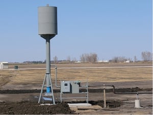 |
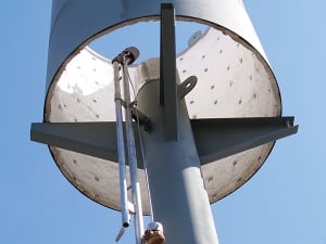 |
| FIGURE 8. Shown here (above left and top) is a small, elevated enclosed flare that operates in a “smokeless,” air- assisted type | |
Mercury and dioxins
Mercury and air toxics (MATS) regulations have impacted coal boilers in a big way. The usual approach to managing mercury is to inject powdered activated carbon (PAC) upstream of fabric filters and ESPs. PAC producers have made major expansions over the past five years to keep up with demand. PAC is effective at temperatures up to 350°F. Higher than that, heat desorbs the mercury. Typical carbon-injection rates are 2 to 5 lb/million acf (actual cubic foot) of stack gas, varying with the amount of mercury in the coal and type of particulate filter.
Wet scrubbers can be used to remove elemental mercury if they are equipped with cooling towers to reduce stack exit temperatures to the required level. Meanwhile, dioxins are formed from organic chlorine in the feedstock, and even inorganic chlorine forms some HCl and Cl2 in high-temperature combustion processes. The solution here is twofold — keep baghouse or ESP temperatures below 450°F to limit “de novo” formation from the chlorine in the stack gas, and use PAC or catalyst-coated filters to remove it.
Multi-pollutant control
While individual APC components can be placed in series to get the job done, single units with multiple capabilities also exist. An example are filters for PM removal, combined with urea or ammonia injection for NOx control and 1-in. thick catalytically treated filter walls. Temperatures of 400°F are preferred for dry-reagent injection for SO2 removal (Figure 10). Yet another firm sells filter bags with a coating that removes dioxins. Activated carbon can be added for mercury and dioxin removal.

FIGURE 9. This three-chamber RTO, with 95% heat recuperation, has the ability to capture and treat fumes when the valve change over occurs to reverse the direction of flow

FIGURE 10. This example of an all-in-one, multi-pollutant-removal system uses reagent injection and catalytic bag filters
Auxiliary systems
Fans and blowers. These components are of prime importance because they move both the air into a combustor and the fluegas or process vent streams out of it. Combustion air is supplied by either a forced-draft fan, an induced-draft fan or both.
Fans may be driven by electric motors or in large sizes, steam turbines. The speed of the fan may be variable or fixed. Fixed-speed fans and blowers control air flow via a mechanical damper on the inlet to the fan, while variable-speed systems control air flow by changing the shaft speed. Variable-speed drives (VFDs) are popular, due to decreased power costs when compared to damper flow control. Gas temperature, fan alloy, resistance to corrosion, and sound level must be figured into the fan specifications.
Power required for the induced draft (ID) fan is equal to flow times pressure drop. In most applications, the flowrate of fume is fixed, however, pressure drop — and power consumption — varies widely with the control device. Table 1 provides some typical pressure drop values. As can be seen, venturis are not a good choice at high pressure drops, and even then, may struggle to remove very fine particles.
Mist and aerosol eliminators. Gas leaving a wet scrubber or a condenser will contain mist and fog droplets. A mist-elimination unit or entrainment separator is used to remove them. Such devices typically use a wire or plastic mesh pad, or a series of baffle plates, which intercept the mist and allow them to coalesce into larger droplets, which then drain from the system.
Removal of very small aerosol droplets (less than 1-micron size), such as SO3/H2SO4, require the use of coalescing mist-eliminator “candles” or mats made of a thick, dense packing, and this often results in correspondingly higher pressure drops and power requirements. An IWS can also remove submicron liquid aerosols and reduce stack opacity. Some states require (and some operating companies prefer) to have a clear stack (for example, a high-tech chip maker operating in the middle of a city). Wet scrubbers typically produce a white steam plume, and this can be eliminated by adding a heat exchanger or stack burner. Finally, in addition to the “front half catch” of hard, dry particulate matter in the front of an EPA test train, some permits require measurement of the “back half catch” of condensable liquids. Unfortunately, these include “pseudo particulates” that do not exist in the stack but rather are formed in the cooled test train impingers. The author has had success working out this issue with regulators when the failure was due to pseudo — not real — condensables.
Stacks. Predicted ground-level pollutant concentrations per dispersion models can be high and unacceptable if there is downwash due to nearby structures. Hence, we suggest stacks be at least 75 ft tall. Per codes, at a bare minimum, they must be 10 ft above nearby equipment and roof tops; this is to protect personnel and air intakes. Even if the current permit is not subject to dispersion, it may be subject to it in the future. Downdrafts can also trigger complaints from nearby neighbors by bringing emissions to ground level.
For testing, it is important to design in two test ports at 90 deg to each other, each with a minimum 3-in. dia., with stack clips to aid stack testers in their test work, with a minimum of 2 diameters upstream and a half diameter downstream of unobstructed straight run. Free-standing stacks, installed without the use of guywires, are preferred, in terms of test crew access and general site safety.
Energy efficiency and cost
Total APC costs include costs related to capital expenditures, operating costs, maintenance costs and compliance-related expenses. Costing of actual systems is beyond the scope of this article; however, it is worth discussing energy use and power costs via the example discussed next. A process produces a stack gas volume of 35,000 actual ft3/min (acfm) at 60°F. The existing APC system utilizes a venturi scrubber with 10–in. w.c. pressure drop to limit particulate-matter emissions to 0.08 grains/dry std. ft3 (gr/dscf). The fan that drives the system is equipped with a 75-hp motor. A higher particulate matter emission-removal efficiency is now required to limit emissions to 0.02 gr/dscf. Two options can be considered: Downsize the venturi throat and increase the pressure drop on the venturi system to 60–in. w.c. to improve particulate removal, or replace the venturi with a baghouse filter. Table 2 shows the power required for the current system, as well as the two options.
In this example, it is clear that the baghouse has significant power savings compared to the high-pressure drop venturi. The same would be the case for an IWS, should a wet system be desired.
What might have been the right choice years ago — a low-pressure drop venturi — is now the wrong choice, based on lowered particulate limits and energy cost for applications with high loading of fine particles. With proper bag selection and maintenance, many baghouses are capable of limiting stack emissions to 0.01–0.02 gr/dscf range, allowing for tighter regulations and for reduced total annual emissions.
Closing thoughts
When selecting new APC or upgrading old, look first at your regulatory limits, then factor in the characteristics of the fume, and all the pollutants that must be controlled. Then select candidate systems, and estimate capital and operating costs before making your final, well-informed choice. n
References
1. McGowan, Thomas F., D. Coughlin, B. Axon, T. Wechsler and J. Santoleri, VOC Emission Controls for the CPI, Chem. Eng., February 2007.
2. McGowan, T., Chief Editor, “Biomass and Alternate Fuels Systems: An Engineering and Economic Guide,” AIChE/John Wiley & Sons, 2009, ISBN: 978-0-470-41028-8. Associate Editors Brown, M., Bulpitt, W., and Walsh Jr.
3. McGowan, Thomas F., Charting a Path for Cost-effective NOx Control, Chem. Eng., October, 2004.
4. U.S. EPA AP-42, Emission Factors; by chapter and fuel type (www.epa.gov/ttn/chief/ap42/ch01/) and by industry (www.epa.gov/ttn/chief/ap42/).
5. McGowan, Thomas F., VOC and Air Toxics Control by Oxidation and Other Methods, Air Pollution Control, September 2014.
6. McGowan, Thomas F., Oxidizers for Control of VOCs and Other Air Toxics: Application and Design, Process Heating, October 2013.
7. “Industrial Ventilation: A Manual of Recommended Practice for Design,” 28th Ed., www.acgih.org/
Author
 Thomas F. McGowan is president and founder of TMTS Associates Inc. (399 Pavillion St., Atlanta, GA 30315; Phone: 404-627-4722; Email: [email protected]; www.tmtsassociates.com), a firm that specializes in thermal systems and air-pollution control. He was previously employed by RMT/Four Nines, the Georgia Tech Research Institute, and Particulate Solid Research, Inc. McGowan has 40 years of experience in air-pollution control, filtration, combustion, and bulk-solids handling. He holds an M.S.Ch.E. from Manhattan College in New York City, and an M.S. in industrial management from Georgia Tech.
