Any loss of containment for liquefied petroleum gas (LPG) can have potentially catastrophic results. This article details various LPG storage configurations with special focus on the design of mounded-bullet systems
Liquefied petroleum gas (LPG) is a mixture of propane and butane, normally found in the ratio of about 60% propane to 40% butane. It is used primarily as a fuel for cooking, industrial systems, auxiliary/backup power systems and other applications. Storage of LPG is a prime concern in petroleum refineries and logistics terminals (Figure 1), because any accidental leak can lead to catastrophic explosions, likely resulting in a boiling-liquid expanding-vapor-cloud explosion (BLEVE).
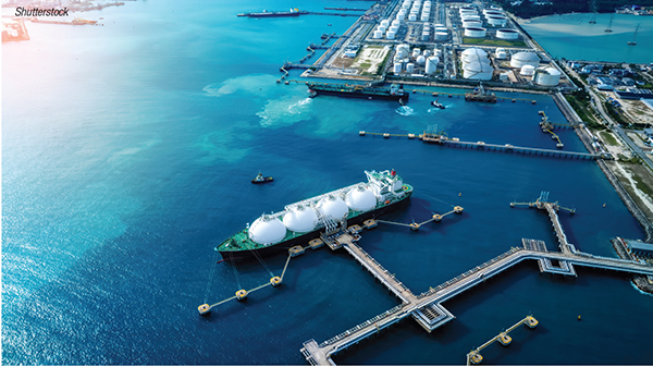
FIGURE 1. Large volumes of LPG are transported and stored within shipping and marketing terminals all over the globe
It should always be borne in mind that even though LPG is transported and stored as liquid for economy and convenience, it is a gas when liberated at normal atmospheric temperature and pressure, and in case of emergency, it should be treated as gas and not as liquid. This article provides some guidance in LPG storage best practices to help avoid unsafe scenarios.
LPG handling areas
Any area where LPG is handled should follow stringent safety practices. Below are some of the common facility types and handling areas where LPG might be encountered.
Petroleum refineries. Propane and butane are commonly produced in crude distillation columns and transferred to large-capacity storage tanks for loading into ships and trucks at export terminals. These storage tanks are typically the mounded-bullet type, which are discussed at length in this article.
LPG import terminals. Propane and butane imported in large marine vessels are typically unloaded through marine loading arms and pumped to shore through pipelines and stored in mounded-bullet storage tanks separately. After heating the propane and butane using seawater flowing through titanium heat exchangers, the propane and butane are then mixed at the required proportions to match customer specifications. The hot seawater is sent back to sea.
Marketing terminal. The LPG received at marketing terminals, either from a petroleum refinery or import terminal, is distributed via pipelines to LPG bottling plants, from which it is subsequently distributed to a municipal gas-distribution system or through cylinders.
LPG bottling plants. LPG bottling plants are located at strategic locations to receive LPG in moderate quantities at mounded bullets and are filled in cylinders using carousels and belt conveyors.
Storage options for LPG
There are three primary storage configurations for LPG, which are summarized in Table 1 and discussed further in the following sections.

Aboveground, ambient-temperature pressurized storage tanks. These tanks typically have cylindrical or spherical geometry (Figure 2). Aboveground, ambient-temperature storage is used for storing smaller volumes of LPG, in the range of around 5–100 metric tons (m.t.), whereas aboveground cryogenic storage is used for storing larger volumes of LPG — around 5,000 m.t. or above.
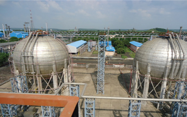
FIGURE 2. Spherical tanks are typically used for storing smaller volumes of LPG
Aboveground, cylindrical atmospheric cryogenic storage. LPG is stored in these tanks at –45ºC and a design pressure of atmospheric pressure plus 1,500 mm H2O. However, the tank is operated at lower pressures of around 500 to 800 mm H2O. Boil-off gases arise out of the storage tank due to heat ingress from atmospheric temperature and material-enthalpy changes. These gases can be compressed by pressure boiloff or holding compressors and cooled using the Joule-Thomson effect. The gas can then re-enter the tank, thus maintaining the tank at atmospheric pressure and cryogenic temperature.
There are two walls for each tank with an annular space of 800 mm. The outer tank has a domed roof and the inner tank has a deck suspended from the outer dome roof, which covers the inner tank at the top. Product is stored in the inner tank, and in the event of inner tank failure, the outer tank is also capable of storing the product. This tank configuration is known as a double-wall double-integrity tank.
The philosophy of storing LPG is the same as for ammonia, ethane, propylene and other gases, although these storage options will vary in terms of the tank’s material of construction.
Mounded bullets. Mounded bullets are aboveground storage tanks for storing large amounts of LPG in horizontal cylindrical vessels, which are buried under sand, rubble and in between retaining walls. The inlet and outlet to these storage tanks are provided with remote-operated shutoff valves (ROSOVs) on the bullet-first body-isolation valve. This provides an intrinsically passive and safe environment and eliminates the possibility of BLEVE occurrence.
Large amounts of LPG are stored in these tanks because they are protected against sun radiation and fire engulfment, radiation from a fire in close proximity and acts of sabotage or vandalism [1]. The area of land required to locate a mounded system is minimal compared to conventional storage. These storage tanks are designed for temperatures ranging from –45 to 55ºC. In some facilities, mounded bullets are stored in parallel (Figure 3) with capacity up to 12,000 m.t., with a maximum of six bullets in a mound.
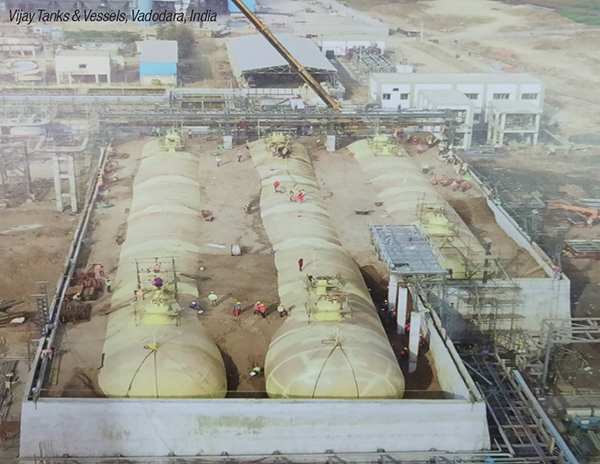
FIGURE 3. Mounded bullets are covered with sand and pebbles to help protect them against damage due to sunlight, vandalism and fire
Instrumentation
Normally, storage tanks are to be filled with LPG up to 85% volume only, with the remainder being vapor space. The storage tanks should be provided with a local pressure indicator (PI), temperature indicator (TI) and mechanical gauge for liquid level measurement. Servo gauge and radar-type level gauges can also be installed. All the pressure gauges should be fitted with excess-flow check valves (EFCV) to shut off the mounded bullet in case the PI is accidentally detached from the tank. Liquid level is indicated in the control room, and various interlocks are provided for low-level and high-level control to protect the mounded bullet. All instrument controls’ local indication should be provided on the top of the mound and should also be repeated in the pump house and control room. Pressure transmitters must also be fitted with double isolation valves and excess-flow EFCVs to protect the facility from accidental release of LPG.
LPG detectors. A minimum of one LPG gas detector should be installed on each exposed portion of the vessel. However, if the nozzles are covered in a dome, each group should have at least two detectors [1].
Pressure relief valves
Pressure relief valves (PRVs) are provided for the mounded bullet to protect against overpressurization. The relief capacity of the combined PRVs is typically designed to be only one third of the relief capacity of a conventional aboveground LPG storage tank. This is the main advantage of the LPG mounded bullet. It also reduces the firefighting equipment sizing. The PRV is sized for 30% of the capacity required for an equivalent size of conventional aboveground vessel.
The discharge of the PRVs should be connected to a flare system wherever available. PRVs should also have lock-open (or car-seal open) isolation valves on both sides of the PRV. In the discharge line of the PRV, a weep hole should be provided to drain any water accumulation, such as from rain.
High venting from PRVs shall be placed a minimum of 3 m above the top of the mound or an exposed nozzle, whichever is higher, for better dispersion of released or vented LPG. Normally, the pressure safety valve (PSV) discharge is to be routed to high vent in small-capacity installations or to an elevated flare located at a safe distance for larger-capacity installations.
There are two types of PRVs used to protect mounded bullets: spring-loaded and multi-port. Ordinary spring-loaded relief valves are very common in industry, and are governed by codes developed by the American Petroleum Institute (API; Washington, D.C.; www.api.org) (API 520, 521 and 526) for sizing and installation [2, 3].
Multi-port relief valves are mounted on the dome of the bullet with only one nozzle opening on the bullet. They have a fixed capacity as specified by the vendor. After calculating the total relieving capacity required for the bullet, either for the fire case or blocked discharge and overpressurization case, whichever is governing, the total required capacity is divided by the capacity of each port and the number of ports to be lined up is calculated. The remaining ports are spares and can be lined up or taken for maintenance without dismantling the multi-port relief valve (Figure 4). This is the main advantage of multi-port relief valves over conventional types of spring-loaded relief valves.
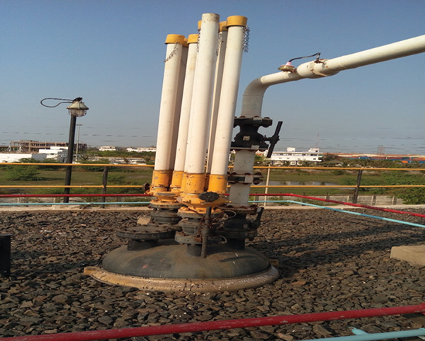
FIGURE 4. Multi-port PRVs enable port maintenance without dismantling the entire valve assembly
Fabrication
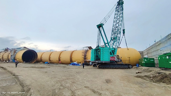
FIGURE 5. Mounded bullets are fabricated from carbon-steel plates. Cranes are used to pull the pieces together inside a retaining wall
Mounded bullets are fabricated by welding multiple sections of cylindrical portions together. Each cylindrical piece is in turn fabricated using steel plates (usually 2.5 m wide and 6 m long), which are bent and welded to form the cylindrical parts (Figure 5). The individual cylindrical pieces are brought together with the help of cranes and placed inside the retaining wall (Figure 6). The pieces are connected by radial welding, followed by 100% radiography, a type of non-destructive test (NDT) to inspect weld integrity. After a sand-blasting surface-preparation step, the surface is painted. The selection of plate dimensions depends on the principle of reducing the wastage of steel in the overall fabrication of mounded bullet. Low-temperature carbon steels (LTCS) are used as the material of construction for the bullet shell.
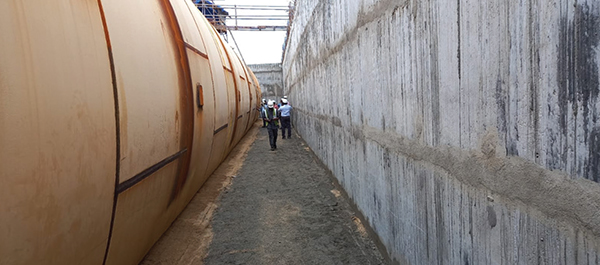
FIGURE 6. Mounded bullets are placed inside a retaining wall prior to welding and radiography inspection
Benefits of mounded bullets
Because the LPG-containing bullets are covered with rubble and sand, the tank surfaces are not directly vulnerable to sun radiation or flame impingement [1].
As a result, the bullet wall, and subsequently, the LPG itself, will not heat up, meaning that vapor generation inside the bullet is controlled. Since the probability of vapor generation is decreased, the relief rates used for sizing relief valves can be assumed as 30% of the relief load of the normal bullet aboveground (without mounding). Substantial savings are gained because of this, due to the smaller PRV sizes and the lower load on the flare system, which necessitate a lower flare height and lower associated costs.
Other design considerations
Design of such pressure vessels is governed by industry codes ASME SEC. VIII Div. 1 or PD 5500 or equivalent, as duly approved by the appropriate authorities. A single code should be adopted for design, fabrication, inspection and testing of all mounded bullet tanks at a facility.
Sizing. The size of a mounded bullet is selected according to the volumetric capacity of LPG to be stored in the facility.
Siting and coverage. The site of a mounded bullet is selected based on soil-bearing capacity (SBC), soil settlement with LPG or water inside the bullet and other parameters like the length and diameter of the bullet. The mound is to be suitably covered and sloped so as to drain the rainwater so that bullet will not dismount and float, and subsoil surface water cannot enter the mound [1].
Cathodic protection. The mounded surface of bullets should be cathodically protected to prevent damage from corrosion.
Nozzles, flanges and manways. All nozzles on the bullet top should be approachable from the top of the mound. To avoid static electricity issues, flanges should be equipped with copper jumpers and piping should have an earthing-strip connection. Two manways must be provided on the mounded vessel for easy maintenance during decommissioning.
Pumping system. Normally, vertical barrel pumps are used for LPG service to increase the net positive suction head available NPSH(A) for better pumping and to avoid cavitation. Also, inlet/outlet valves are provided along with ROSOVs and must be failsafe and enclosed in fireproof box connected with fire-retardant cables. A pumphouse for an LPG storage installation is shown in Figure 7. ■
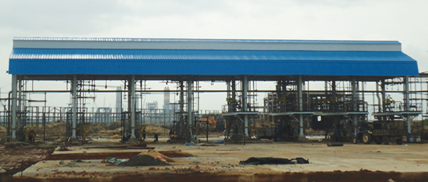
FIGURE 7. A pumphouse is an essential element for LPG storage installations. Typically, vertical-barrel pumps are the preferred pump option
References
1. Oil Industry Safety Directorate (OISD), Standard 150, Design and Safety Requirements for Liquefied Petroleum Gas Mounded Storage Facility, Sept. 2021
2. API 520, Sizing, Selection and Installation of Pressure-Relieving Devices, Part II — Installation, 6th Ed., March 2015.
3. API 521, Pressure-Relieving and Depressuring Systems, 6th Ed., January 2014.
4. API 2000, Venting Atmospheric and Low-Pressure Storage Tanks, 7th Ed., March 2014.
5. API 2510, Design and Construction of LPG Installations, 9th Ed., August 2020.
Author
 Koya Venkata Reddy is currently the deputy general manager, Process, at FACT Engineering and Design Organization in Kochi, India (FEDO; Email: [email protected]). He holds an M.B.A. in finance from Indira Gandhi National Open University (IGNOU) in New Delhi and an M.S. in project management from Cochin University of Science and Technology (CUSAT) in Kochi. He joined FACT in 1991 and has three decades of experience in the areas of plant operations, troubleshooting, optimization, process design, chemical plant revamps, process simulations, energy audits and so on. Reddy is a long-term member of the Indian Institute of Chemical Engineers (IIChE), FACT Technical Society and is active in many other industry organizations. He is also currently a faculty member at the FACT Training Center for Safety Audits.
Unless otherwise noted, all images provided by author.